An Experimental Study of the Dielectric Premiability of Dry Saturated Steam
*NPO YuMAS, ul. Yartsevskaya 29, korp. 2, Moscow, 121552 Russia
** Moscow Power Engineering Institute, lit. Krasnokazarmennaya 14. Moscow, 111250 Russia
Abstract — The results from experimental studies of the dielectric premiability of dry saturated steam in the temperature range from 388 to 614 К are presented, based on which an equation for calculating this constant is proposed.
DOI: 10.1134/S0040601511040082
Additional information on the state of working fluid used at nuclear and thermal power stations is required for improving their control systems. Traditional thermodynamic parameters such as pressure and temperature cannot provide adequate information about its state when phase transitions occur over the larger part of working paths in the overwhelming majority of power installations. In a once-through boiler for example, neither pressure nor temperature can provide adequate information on the density of coolant over at least 60% of the boiler path length, because this coolant exists there in the forms of boiling water, wet steam (the state of which varies from small bubbles in water to fine inclusions of water in steam), and dry saturated steam. In nuclear power installations, wet steam is the main working fluid. The majority of other kinds of thermal power equipment (e.g., refrigerating plants, heat pipes, etc.) have functional cycles on the basis of phase transitions.
Techniques based on measurements of electrophysical parameters are among the most promising and best developed methods for monitoring the state of two-phase mixtures. This is confirmed by a large volume of data obtained from experimental studies of water coolant in different phase states carried out using these methods [1—3]. Dielectric constant s occupies a special place among electrophysical parameters [4]. In addition, s is a macroparameter characterizing intermolecular interaction in substance, and its value allows a judgment to be made about structural changes in it. The parameter e is also used in calculations of chemical processes in coolant. The value of the complex dielectric premiability depends on the standardized indicators of water chemistries, and its real component gives information on the electrical conductivity of the medium.
The dielectric premiability of water coolant is a sensitive parameter and changes its value even if small concentrations of the liquid phase appear in steam [ 31.
The procedure for calculating the s of water and steam is determined by the equation proposed in [5], which is based on the Debye formula with an empirical correlation coefficient of interaction between molecules. This equation was obtained by processing a body of experimental data the claimed error of which is in the range 0.6—5% [6]. Unfortunately, this body of data contains an insufficient amount of information on the s of dry saturated steam. The present work is intended to replenish the body of data on the dielectric constants of water and steam and to confirm or refute the applicability of the equation from f 51 for calculating the s of dry saturated steam.
The aim of this study is to obtain experimental data on the dielectric constant of dry saturated steam with an error of not more than 0.3%. The experimental setup for this purpose was developed on the basis of experience gained at the Moscow Power Engineering Institute (MEI) [3] (Fig. 1).
The autoclave with an outer diameter of 60 mm and length of 150 mm is made of stainless steel. The upper end of the device has been sealed by argon-arc welding. The autoclave is surrounded on its outer side by a temperature-damping shell on which electrical heaters are mounted. The entire autoclave is covered by a layer of heat insulation to prevent heat losses into the surrounding medium.
The working unit includes a measurement cell (Fig. 2), fixing assembly, and separation mesh. The measurement cell, whose capacitance in vacuum is C0 = 30 pF has a rigid design and allows the studied body to be freely inserted in the interelectrode space. Two cylindrical electrodes made of stainless steel are arranged coaxially on the base using spacer bushings. The bushings are made of aluminum oxide A1203, which is insoluble in aqueous solutions and has high dielectric characteristics.
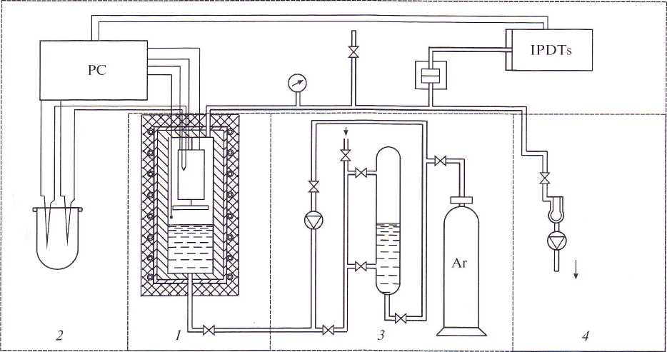
Fig. 1. Schematic diagram of the experimental setup. (1) Autoclave with the working unit, (2) parameter measurement and recording system, (3) working fluid preparation system, and (4) vacuum unit. PC is a personal computer and IPDTs is a pressure measurement instrument.
The protective ring is galvanically connected to the base, which, in turn, is secured to the autoclave lower generatrix by welding (the autoclave body is grounded). The cell’s lower end face is furnished with a protective mesh, which prevents occasional ingress of liquid droplets into the interelectrode space.
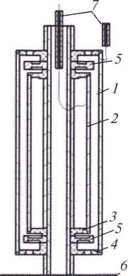
Fig. 2. Measurement cell. (1) and (2) outer and inner electrodes, (2) base, (4) spacer bushing, (5) safety rings, (6) separation mesh, and (7) electric inlets.
Electrical connections are taken into the zone of high parameters by means of electric inlets. A ceramic base into which a platinum wire is sintered in accordance with the method proposed in [3] serves as the main element of these inlets.
The design feature of the autoclave is that it has a system of three electric inlets mounted on the upper end face of the device, which eliminate the stray capacitances of the inlet.
The serviceability of the measurement cell was checked by measuring the dielectric constants of polar gases according to the procedure described in [3]. The stability of the measurement cell’s electrical capacitance was also checked at different frequencies by means of an E8-2 transformer bridge to ascertain the stray components.
The influence of temperature deformations of the cell in the temperature range 388—615 К was approximated by a linear dependence and corrected in the course of experimental studies according to the procedure described in [7].
The electrical capacitance C0 was determined using dielectric calibration liquids.
The temperature of working fluid inside the autoclave was checked and measured using Chromel— Alumel thermocouples placed in the autoclave inner cavity at different levels over its height. The level of liquid phase was recorded by a system of single-electrode contact sensors (the grounded autoclave body served as the second electrode). The pressure was measured through a separating membrane by an IPDT instrument having the accuracy class 0.07.
The capacitance of the cell filled with dry saturated steam was recorded using an R-5083 transformer bridge, the operation of which in the selected measurement range corresponds to the accuracy class 0.02. The basic permissible measurement error of the bridge does not exceed 0.15%. The measurements were carried out at the basic nominal frequency equal to 10 kHz and also at a frequency of 30 kHz.
The resulting error of the dielectric constant measurement system is determined as consisting of three components: the measurement circuit itself (the transformer bridge) equal to 0.15%, the measurement cell, including the errors of determining the useful capacitance and edge effects equal to 0.17%, and the effect of stray capacitances of the connection lines equal to 0.15%. The rms error was equal to 0.28%.
The working fluid preparation system and the vacuum unit include glass vessels for degassing liquid, a VN-2MG plunger pump (see Fig. I), a nitrogen trap, and a V1T-1A vacuum meter.
The procedure for measuring the dielectric premi- ability of dry saturated steam is reduced to determining the cell capacitance in vacuum C0, which with the correctly assembled installation must correspond to the value obtained using calibration liquids and the capacitance of the cell C filled with the studied substance. The dielectric constant is defined as the ratio C/C0.
The measured parameters, including the cell’s electrical capacitance, are transmitted to the personal computer.
The measurements were carried out as follows. After checking all components of the experimental installation, it was filled with working fluid, and then the supply voltage was applied to the electric heaters, after which the installation was held until the temperature parameters became stable. After that, the thermodynamic and electrical parameters were recorded. The obtained experimental data are summarized in the table. It is clearly seen that the obtained experimental values of s for dry saturated steam are in good agreement with the results of calculations carried out using the equation given in [5]. Only for four points is the deviation Д [(sexp - £caic)/£exP] x 100%] equal to around 0.5, and for two points does it reach 0.7%.
Figure 3 shows a comparison between the results of calculations s using the equation from [5] and the experimental data [8—10] obtained by other researchers. These data are also in good agreement with each other.
The results of comparison can be represented more vividly as the functions s = /(p/7) [7] and A =/(p/7) (Fig. 4).
Results from experimental studies of the dielectric prenriability of dry saturated steam and their comparison with data calculated using the equation from [51]
|
Г, к |
p, MPa |
p, kg/nr' |
^exp |
^calc |
|
388.45 |
0.171000 |
0.97 |
1.000 |
1.009 |
|
424.75 |
0.497000 |
2.65 |
1.018 |
1.023 |
|
429.80 |
0.568000 |
3.01 |
1.021 |
1.026 |
|
430.77 |
0.582000 |
3.08 |
1.022 |
1.027 |
|
436.03 |
0.665000 |
3.49 |
1.026 |
1.030 |
|
438.56 |
0.709000 |
3.71 |
1.029 |
1.032 |
|
439.81 |
0.731000 |
3.82 |
1.029 |
1.033 |
|
442.34 |
0.777000 |
4.05 |
1.031 |
1.034 |
|
443.35 |
0.797000 |
4.14 |
1.032 |
1.035 |
|
445.86 |
0.846000 |
4.38 |
1.035 |
1.037 |
|
447.12 |
0.872000 |
4.51 |
1.036 |
1.038 |
|
449.61 |
0.925000 |
4.77 |
1.038 |
1.040 |
|
451.00 |
0.955000 |
4.92 |
1.040 |
1.041 |
|
541.30 |
5.436000 |
27.21 |
1.215 |
1.206 |
|
541.73 |
5.472000 |
27.41 |
1.216 |
1.208 |
|
510.27 |
3.184000 |
15.91 |
1.125 |
1.123 |
|
525.09 |
4.112000 |
20.65 |
1.162 |
1.158 |
|
530.10 |
4.469000 |
22.51 |
1.176 |
1.171 |
|
541.06 |
5.331000 |
27.11 |
1.211 |
1.205 |
|
548.78 |
5.919000 |
30.84 |
1.235 |
1.233 |
|
563.60 |
7.498000 |
39.42 |
1.302 |
1.298 |
|
574.35 |
8.743000 |
47.10 |
1.358 |
1.358 |
|
586.67 |
10.359000 |
57.87 |
1.450 |
1.445 |
|
593.28 |
11.316000 |
64.78 |
1.506 |
1.502 |
|
596.65 |
1 1.829000 |
68.68 |
1.540 |
1.536 |
|
599.14 |
12.220000 |
71.74 |
1.566 |
1.562 |
|
601.94 |
12.673000 |
75.40 |
1.595 |
1.595 |
|
605.73 |
13.305000 |
80.73 |
1.645 |
1.643 |
|
608.50 |
13.782000 |
84.96 |
1.684 |
1.682 |
|
609.48 |
13.954000 |
86.52 |
1.698 |
1.696 |
|
609.91 |
14.031000 |
87.22 |
1.704 |
1.703 |
|
610.86 |
14.201000 |
88.80 |
1.717 |
1.718 |
|
611.61 |
14.335000 |
90.07 |
1.727 |
1.730 |
|
612.77 |
14.547000 |
92.08 |
1.745 |
1.749 |
|
613.58 |
14.694000 |
93.53 |
1.758 |
1.763 |
|
613.91 |
14.755000 |
94.13 |
1.763 |
1.769 |
|
614.20 |
14.809000 |
94.66 |
1.768 |
1.774 |
|
614.71 |
14.905000 |
95.61 |
1.779 |
1.783 |
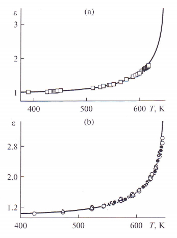
Fig. 3. Comparison between the calculated and experimental values of the E of saturated steam.—Calculation by the equa¬tion from [5]. Experimental data: 0 data from the present study, • data of [S], Odata of [9], and A data of [10].
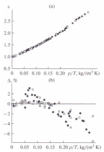
Fig. 4. Experimental data on e (a) and the discrepancy between them and the values calculated by the equation from [5] (b). The notation is the same as in Fig. 3.
The experimental data on the dielectric constant of dry saturated steam obtained in this work are in satisfactory agreement (A <0.7%) with the results of calculations carried out using the equation from [5]. However, the experimental data of other researchers [8— 10] have deviations equal to 4—6 and in some cases even 8%. In addition, at p/T> 0.15, the values of A lie in the negative region, which points to shortcomings of the adopted model. In view of these circumstances, the authors of this paper approximated the body of experimental data for the s of dry saturated steam in the form s =/(p/7). The following equation has been obtained:
e = 0.996785 + 3.697335p/T + 18.13208(p/7)2
- 133.71953(p/7)3 + 573.99166(p/T)4
- 799.05976(p/7)5.
The deviation of the experimental data on the dielectric constant of dry saturated steam obtained in this work and in [6] from the results of calculations using this equation is shown in Fig. 5.
The values of A lie predominantly in the interval ±1.5%, and only a small part of them reaches 2%. The maximal discrepancy between the experimental and calculated results is equal to 2.7% for one experimental point from [9] lying in the near-critical region (T=
643.11 K). This gives us grounds to speak about good agreement between the calculation model and experimental data.
Thus, the obtained experimental data on the dielectric constant of dry saturated steam have a high degree of trustworthiness and are well described by the proposed equation of the form s = /(p/7).
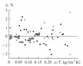
Fig. 5. Discrepancy between the experimental data on the dielectric constant of dry saturated steam and the values calculated using the proposed equation. Q Experimental data obtained in this study and in [6]. The meaning of data denoted by 5, and A is the same as in Fig. 3.
ACKNOWLEDGMENTS
The authors are grateful to Cand. Tech. Sci. O.V. Belyaeva for help in processing the results of studies and for the presented graphic materials.
REFERENCES
- VI. Subbotin, Yu. E. Pokhvalov, D. E. Mikhailov, et al., “On Calculating the Gas Content in a Mixture from the Data of Measurements Carried Out Using the Resistive and Capacitive Methods,” Tepioenergetika, No. 4, 70— 75 (1975) [Therm. Eng., No. 4 (1975)].
- В. I. Nigmatulin, A. A. Vinogradov, V. A. Vinogradov, and Sh. E. Kurbanov, “A Technique for Measuring the Thickness of Liquid Film and Wave Characteristics of Its Surface in Steam—Water Flow,” Teplofiz. Vys. Temp. 20 (6), 1145-1152 (1982).
- B. P. Golubev, S. N. Smirnov, Yu. M. Lukashov, and E. P. Svistunov, Electrophysical Methods for Studying the Properties of Coolants (Energoatomizdat, Moscow, 1985) fin Russian].
- V. A. Viktorov, В. V. Lunkin, and A. S. Sovlukov, The High-Frequency Method for Measuring Nonelectrical Quantities (Nauka, Moscow, 1978) [in Russian].
- D. P. Fernandez, A. R. H. Goodwin, E. W. Lemmon, etal., “A Formulation for the Static Permittivity of Water and Steam at Temperature from 238 К to 873 К at Pressures up to 1200 MPa, Including Derivatives and Debye—Hukel Coefficients,” J. Phys. Chem. Ref. Data 26, 11-25 (1997),
- D. P. Fernandez, Y. Mulev, A. R. H. Goodwin, and J. M. N. Levelt Senders, “A Database for the Static Dielectric Constant of Water and Steam,” J. Phys. Chem. Ref. Data 24, 33-69 (1995).
- Yu. V. Mulev, Using the Electrophysical Properties of Coolants at Thermal and Nuclear Power Stations in Developing Modern Diagnostic Systems, Doctoral Dissertation in Technical Sciences (MEI, Moscow, 1992).
- E. P. Svistunov, E. P. Golubev, and S. N. Smirnov, “Measuring the Dielectric Constant of Steam on the Saturation Line,” Tepioenergetika, No. 6, 69—70 (1974) [Therm. Eng., No. 6 (1974)].
- Yu. M. Lukashov and V. N. Shcherbakov, “Studying the Dielectric Constant of H20 at Temperatures from 573 to 873 К and Pressures up to 170 MPa,” Tepioenergetika, No. 3, 70-71 (1980) [Therm. Eng., No. 3 (1980)].
- M. R. Mushailov, Determining the Dielectric Constants of Aqueous Gas Solutions Used in Power Engineering and Drawing Up Reference Tables, Candidate’s Dissertation in Technical Sciences (MEI, Moscow, 1988).