Monitoring steam-water flows by a dielectric method
Yu V Mulev
Belorussian Polytechnic Institute
Improvement of the operating modes of power plant is in some cases held back by the lack of representative information on state of the working medium. One of the parameters characterising this state is the dryness fraction of wet steam, expressed volumetrically by cp or on the mass basis by x. Various methods have been used successfully in the laboratory for monitoring steam-water flows, conductometric, optical, acoustic, etc. However, lack of instruments meeting the demands of industrial applications has impelled the development of new versions of instruments or improvement of existing ones. The work described here was devoted to a dielectric method of measuring dryness fraction of wet steam.
This method can be based both on measuring dielectric constant and on determining tangent of the angle of dielectric losses. In wet- steam applications the latter has been studied very little, also the angle of dielectric losses is affected to a considerable extent by solids content of the medium. It is therefore best to use dielectric constant E, measured at high frequencies, where the effect of tangent of the angle is minimal.
The primary transducer is in the form of a capacitance and consists as a rule of two electrodes. At present the instruments are designed for diagnostic work in small pipelines, of diameter 10 to 40 mm, while for pipes of large diameter sampling units are required. The best arrangement for monitoring flows in pipelines is one with coaxial primary transducers, as shown in Fig. la. The key to this and Fig. lb is: a, main transducer; b, compensating transducer; 1, supply tube; 2, casing; 3, internal electrode; 4, external electrode; 5, cap; 6, electrical input; 7, connector. The medium is supplied through the inter-electrode space where there is a capacitance proportional to the quantity of liquid phase and the pressure of the medium. The compensating transducer has the same geometric dimensions as the main one, and is designed to eliminate the interference factors which include pressure of the medium and capacitance of the electrical input and the supply connections. Its distinguishing feature is that the steam in the inter-electrode space is maintained in a dry saturated state at a pressure equal to that of the test medium (Fig. lb).
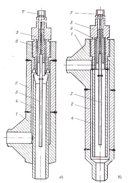
Figure 1. The main and compensating primary transducers of the dielectric instrument.
In the experimental investigations the range of electrophysical properties of wet steam studied was dictated by the industrial application requirements: pressure from 5.88 to 14.70 MPa, mass dryness from 0.5 to 1.0, mass velocity from 500 to 2100 kg/m2.s. The procedure involved preparing flows of superheated steam and dry saturated steam, measuring their electrophysical properties and comparing the results obtained with already known results. In the next stage, superheated steam was cooled in the surface-type heat exchangers of the apparatus by water. A heat balance method was used to calculate mass dryness fraction of the flow leaving the heat exchangers and at the same time at a distance of about 300 diameters from the outlet capacitance component C of the primary transducer was measured, with subsequent conversion to E. Initial capacitance of the transducer was 22.17 pF. Mass dryness was varied within the desired range by varying the cooling water and superheated steam flowrates. Mean square error in determining x, ox, was 6.22% and with respect to E, ae was 1.81%. The latter includes the error of calibrating the instrument and the error of the calibrating curve of the secondary instrument.
Investigations were conducted for the isobars 5.88, 8.83, 11.76 and 14.70 MPa with a step for mass dryness fraction of 0.1 units of x. At each point 5—7 measurements were made in the course of 5 —6 series of tests. The results obtained are shown in Fig. 2 and are compared with those from the author’s formulae (3), (4) and (6).
Special tests were made to determine the effect on the results of thickness of the wall-adjacent film of liquid. At p = const and x = const the main factor affecting film thickness is velocity of the mixture. Thus conditions were set up in which p and x were constant and v varied. At p = 5.88 MPa and x = 0.83 flow velocity was varied from 4.2 to 20 m/s; at p = 8.83 MPa and x = 0.87, from 4.8 to 22 m/s; at p = 11.76 MPa and x = 0.93, from 7.4 to 33 m/s. With change in velocity within these limits no differences were noted in the readings of the dielectric instrument although it is clear that further study of this problem is needed.
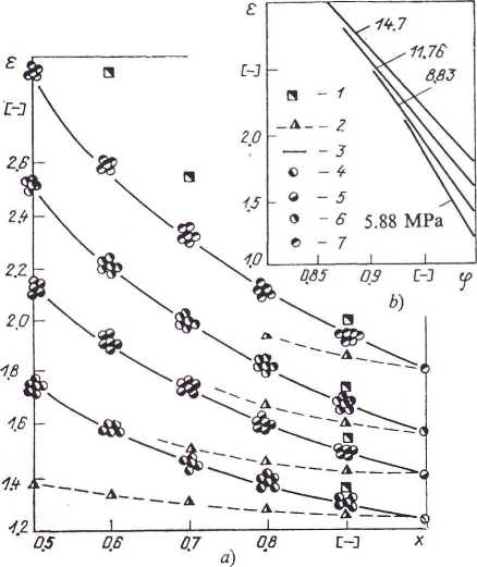
Figure 2. Dependence of dielectric constant on mass dryness (a) and volumetric dryness (b ) of wet steam.
1, calculation from formula (4); 2, calculation from formula (3); 3, calculation from formula (6); 4 — 7, experimental points on
isobars with p = 5.88, 8.83, 11.76 and 14.70 MPa respectively.
Industrial testing of the instrument was done at Berezovka Central Power Station, on No. 7 boiler which includes a system of recirculating working medium, designed for intensive unloading. The medium is separated after the lower radiant section, liquid phase being returned to the feedpump suction. The separated steam passes to the middle radiant section. Sampling units were fitted after the separator. The method of testing consisted of stepwise change in flow of feedwater, fuel and medium returned to the feedpump suction. Moisture content of the steam-water flow was recorded by a KSP-4 potentiometer and there was in addition an indicating instrument based on an M-296 millivoltmeter. Testing continued for six months during which minor faults were found, but the instrument proved to be sufficiently reliable and accurate.